Installation of Underground Pipes
In an underground installation, the external soil load above a buried flexible pipe causes a decrease in the vertical diameter and a corresponding increase in the horizontal diameter of the pipe. The horizontal movement of the pipe walls into the soil material at the sides of the pipe develops a passive resistance that acts to help support the external load. The resistance of the soil is affected by the type of soil and its density and moisture content. The higher the soil resistance, the less the pipe will deflect. Proper installation techniques are necessary to develop the passive soil resistance required to prevent excessive pipe deflections. The deflection of a buried flexible pipe depends on the soil load and live load on the pipe, the stiffness of the pipe, the passive resistance of the soil at the sides of the pipe, the time consolidation characteristics (deflection lag factor) of the soil, and the degree of support given to the bottom of the pipe (bedding coefficient).
TRENCH EXCAVATION Excavate trenches to ensure that sides will be stable under all working conditions. Excavated material should be placed away from the trench to minimize the risk of trench wall collapse. It is always a good practice to remove water from a trench before laying and backfilling pipe. When ground water is present in the work area, dewater to maintain stability of in situ and imported materials. Maintain water level below pipe bedding. Trench construction will vary according to the types of soil encountered (stable or unstable). In any case the trench bottom shall be flat and continuous.
Stable trench wall : Trench wall usually can be made vertical from the bed to the top of the pipe without the use of shoring or sheet piling. Unstable trench wall : The trench will be excavated with vertical wall providing sheet shoring. Depending on the conditions of the unstable trench bottom, the installation contractor may require different type of foundations. Trench width: Where trench walls are stable or supported, provide a width sufficient to ensure working room to properly and safely place and compact haunching and other embedment materials. The space between the pipe and trench wall must be wider than the compaction equipment used in the pipe zone. Suggested values for the trench width are as follows; DN ≤ 400 : L = DN + 400 mm
400 < DN < 1000 : L = DN + 600 mm
DN > 1000 : L = DN + 800 mm The trench width in unsupported, unstable soils will depend on the size and stiffness of the pipe, stiffness of the embedment and in situ soil, and depth of cover.
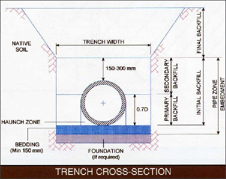
Foundation: Backfill materials placed and compacted in the bottom of the trench to replace over excavated material tabilize the trench bottom if unsuitable ground conditions are encountered.
Bedding: Backfill material placed in the bottom of the trench or on the foundation to provide a uniform material on which to lay the pipe. The bedding should have a minimum thickness of 150 mm.
Backfilling: Initial backfill is divided into two areas; primary backfill from the top of bedding to 70% of the outside diameter of pipe and secondary backfill which extends upto 150-300 mm above the top of the pipe. The final backfill above the pipe zone may be placed without compaction by spreading, in approximately uniform layers, so that the trench is filled completely without any voids.
Haunching: Backfill material placed on top of the bedding and under the springline of the pipe; the term only pertains to soil directly beneath the pipe.
Pipe zone embedment: All backfill around the pipe which includes the bedding, haunching and initial backfill.
Install foundation and bedding as required by the engineer in accordance with conditions in the trench-bottom. Provide a firm, stable and uniform bedding for the pipe barrel and protruding features of its joint. Provide a minimum of 100 mm of bedding below the barrel and 75 mm below any part of the pipe unless otherwise specified. Often the bedding material will have to come from sources other than the native trench material in order to provide the proper gradation and pipe support. The bedding material should be the same material as the initial backfill. Native soil material can be used as a bedding material if it meets the requirements of the initial backfill. When rock or unyielding material is present in the trench bottom, install a cushion of bedding with minimum thickness of 150 mm below the bottom of the pipe. Where the trench bottom is over excavated because of unstable conditions, install a foundation of SC1, SC2 or larger materials. Complete the foundation with a suitably graded material where conditions may cause migration of fines and loss of pipe support. Minimize localized loadings and differential settlement wherever the pipe crosses other utilities or subsurface structures, or whenever there are special foundations such as concrete-capped piles or sheeting. Provide 150 mm minimum cushion of bedding between the pipe and any such point of localized loading. Place pipes and fittings in the trench with the invert conforming to the required elevations, slopes and alignment. In special cases where the pipe is to be installed to a curved alignment, maintain angular joint deflection or pipe bending radius within acceptable design limits, or both. For elastomeric seal joint, verify that pipe ends are marked, to indicate insertion stop position, and that pipe is inserted into pipe or fitting bells to this mark. Protect the end of the pipe during assembly and do not use excessive force that may result in over-assembled joints or dislodged gaskets. Angular deflection should not exceed the allowable limit. Place embedment materials by methods which will not disturb or damage the pipe. Work in and compact the haunching material in the area between the bedding and the underside of the pipe before placing and compacting the remainder of the pipe-zone embedment. Do not permit the compaction equipment to contact and damage the pipe. Use compaction equipment and techniques that are compatible with materials used and location in the trench.
TYPICAL COMPACTION MEHTODS
The following compacting suggestions will enable to achieve the maximum practical material density. Excessive compaction or compaction with inappropriate equipment can result in pipe deformation or pipe lifting off the bedding. Care must be used when compacting the pipe zone backfill with frequent checks of pipe shape.
Coarse grained soils (SC1 & SC2) with less than 5% fines: For coarse grained soil with less than 5% fines, the maximum density results from compacting, saturation and vibration. Further to the use of internal vibrators, heights of successive lifts of backfill must be limited to the penetrating depth of the vibrator. The backfill is placed in lifts of 0.15 to 0.3 m. Pipeline flotation has to be avoided when saturating the pipe zone backfill area. Water jetting will erode side support and few experts recommend it. Placing backfill over the pipe must be avoided, while the pipe zone material is saturated. That would load the pipe before the proper support can develop.
Coarse grained soils (SC2) with 5 to 12% fines: Compacting of coarse grained soils containing between 5 and 12% fines, is carried out such as by tamping or saturation and vibration. The method used should result in the maximum density of the backfill.
Coarse grained soil (SC3 & SC4) with greater than 12% fines: Coarse grained soils containing more than 12% fines, compact test by mechanical tamping in lifts of 0.1 to 0.15 m. In particular for fine grained soils, the soil modulus (passive soil resistance) is density sensitive and a greater compact effort will be required to obtain the necessary proctor density dictated by design.
In an underground installation, the external soil load above a buried flexible pipe causes a decrease in the vertical diameter and a corresponding increase in the horizontal diameter of the pipe. The horizontal movement of the pipe walls into the soil material at the sides of the pipe develops a passive resistance that acts to help support the external load. The resistance of the soil is affected by the type of soil and its density and moisture content. The higher the soil resistance, the less the pipe will deflect. Proper installation techniques are necessary to develop the passive soil resistance required to prevent excessive pipe deflections. The deflection of a buried flexible pipe depends on the soil load and live load on the pipe, the stiffness of the pipe, the passive resistance of the soil at the sides of the pipe, the time consolidation characteristics (deflection lag factor) of the soil, and the degree of support given to the bottom of the pipe (bedding coefficient).
TRENCH EXCAVATION Excavate trenches to ensure that sides will be stable under all working conditions. Excavated material should be placed away from the trench to minimize the risk of trench wall collapse. It is always a good practice to remove water from a trench before laying and backfilling pipe. When ground water is present in the work area, dewater to maintain stability of in situ and imported materials. Maintain water level below pipe bedding. Trench construction will vary according to the types of soil encountered (stable or unstable). In any case the trench bottom shall be flat and continuous.
Stable trench wall : Trench wall usually can be made vertical from the bed to the top of the pipe without the use of shoring or sheet piling. Unstable trench wall : The trench will be excavated with vertical wall providing sheet shoring. Depending on the conditions of the unstable trench bottom, the installation contractor may require different type of foundations. Trench width: Where trench walls are stable or supported, provide a width sufficient to ensure working room to properly and safely place and compact haunching and other embedment materials. The space between the pipe and trench wall must be wider than the compaction equipment used in the pipe zone. Suggested values for the trench width are as follows; DN ≤ 400 : L = DN + 400 mm
400 < DN < 1000 : L = DN + 600 mm
DN > 1000 : L = DN + 800 mm The trench width in unsupported, unstable soils will depend on the size and stiffness of the pipe, stiffness of the embedment and in situ soil, and depth of cover.
 |
Foundation: Backfill materials placed and compacted in the bottom of the trench to replace over excavated material tabilize the trench bottom if unsuitable ground conditions are encountered.
Bedding: Backfill material placed in the bottom of the trench or on the foundation to provide a uniform material on which to lay the pipe. The bedding should have a minimum thickness of 150 mm.
Backfilling: Initial backfill is divided into two areas; primary backfill from the top of bedding to 70% of the outside diameter of pipe and secondary backfill which extends upto 150-300 mm above the top of the pipe. The final backfill above the pipe zone may be placed without compaction by spreading, in approximately uniform layers, so that the trench is filled completely without any voids.
Haunching: Backfill material placed on top of the bedding and under the springline of the pipe; the term only pertains to soil directly beneath the pipe.
Pipe zone embedment: All backfill around the pipe which includes the bedding, haunching and initial backfill.
Install foundation and bedding as required by the engineer in accordance with conditions in the trench-bottom. Provide a firm, stable and uniform bedding for the pipe barrel and protruding features of its joint. Provide a minimum of 100 mm of bedding below the barrel and 75 mm below any part of the pipe unless otherwise specified. Often the bedding material will have to come from sources other than the native trench material in order to provide the proper gradation and pipe support. The bedding material should be the same material as the initial backfill. Native soil material can be used as a bedding material if it meets the requirements of the initial backfill. When rock or unyielding material is present in the trench bottom, install a cushion of bedding with minimum thickness of 150 mm below the bottom of the pipe. Where the trench bottom is over excavated because of unstable conditions, install a foundation of SC1, SC2 or larger materials. Complete the foundation with a suitably graded material where conditions may cause migration of fines and loss of pipe support. Minimize localized loadings and differential settlement wherever the pipe crosses other utilities or subsurface structures, or whenever there are special foundations such as concrete-capped piles or sheeting. Provide 150 mm minimum cushion of bedding between the pipe and any such point of localized loading. Place pipes and fittings in the trench with the invert conforming to the required elevations, slopes and alignment. In special cases where the pipe is to be installed to a curved alignment, maintain angular joint deflection or pipe bending radius within acceptable design limits, or both. For elastomeric seal joint, verify that pipe ends are marked, to indicate insertion stop position, and that pipe is inserted into pipe or fitting bells to this mark. Protect the end of the pipe during assembly and do not use excessive force that may result in over-assembled joints or dislodged gaskets. Angular deflection should not exceed the allowable limit. Place embedment materials by methods which will not disturb or damage the pipe. Work in and compact the haunching material in the area between the bedding and the underside of the pipe before placing and compacting the remainder of the pipe-zone embedment. Do not permit the compaction equipment to contact and damage the pipe. Use compaction equipment and techniques that are compatible with materials used and location in the trench.
TYPICAL COMPACTION MEHTODS
The following compacting suggestions will enable to achieve the maximum practical material density. Excessive compaction or compaction with inappropriate equipment can result in pipe deformation or pipe lifting off the bedding. Care must be used when compacting the pipe zone backfill with frequent checks of pipe shape.
Coarse grained soils (SC1 & SC2) with less than 5% fines: For coarse grained soil with less than 5% fines, the maximum density results from compacting, saturation and vibration. Further to the use of internal vibrators, heights of successive lifts of backfill must be limited to the penetrating depth of the vibrator. The backfill is placed in lifts of 0.15 to 0.3 m. Pipeline flotation has to be avoided when saturating the pipe zone backfill area. Water jetting will erode side support and few experts recommend it. Placing backfill over the pipe must be avoided, while the pipe zone material is saturated. That would load the pipe before the proper support can develop.
Coarse grained soils (SC2) with 5 to 12% fines: Compacting of coarse grained soils containing between 5 and 12% fines, is carried out such as by tamping or saturation and vibration. The method used should result in the maximum density of the backfill.
Coarse grained soil (SC3 & SC4) with greater than 12% fines: Coarse grained soils containing more than 12% fines, compact test by mechanical tamping in lifts of 0.1 to 0.15 m. In particular for fine grained soils, the soil modulus (passive soil resistance) is density sensitive and a greater compact effort will be required to obtain the necessary proctor density dictated by design.